Author(s): Peter J Schubert
Wireless Power Transfer (WPT) is the technique of delivering energy to specific targets with high-gain antennas. An important global application is SpaceBased Solar Power (SBSP) in which powersats in Earth orbit gather sunlight and beam this power to terrestrial groundstations (rectennae). At the distances involved, and the power levels needed to be economical, any stray (off-axis or off-target) energy can disrupt communications, giving cause for regulatory restriction or public objection of SBSP. Until recently, sidelobe levels (SLL) were limited to no lower than -60 dB, meaning that a gigawatt beam would give off kilowatt-range SLL, leading to desensitization of communications devices for a very wide radius surrounding a rectenna. The author discovered, published, and validated a specific design for a phased array antenna (PAA) that allows SLL to be reduced to -240 dB, creating what is called a "pencil beam" with negligible off-axis energy. Studies have found that this method can be applied to PAA as small as 6 m diameter at 5.8 GHz. This breakthrough discovery was first published in 2016 but appears to have largely escaped notice by the WPT community. The second issue is aiming accuracy, with the de facto solution being phase conjugation at the transmit PAA using a pilot beam issued from the receiver. While elegant, the accuracy of angle of arrival (AOA) using phase conjugtion is limited to about 1 degree (17 milliradians). This is sufficient for 5G signals over 100s of meters, but grossly inadequate for SBSP that requires microradian pointing accuracy. A novel method to detect AOA at the microrad scale that is separated from the transmitter emission electronics allows independent optimization of both. This work presents simulation studies showing microradian capability and laboratory results in the single millirad range, a factor of 10 improvement over the current state of the art. With this new approach, an orbiting powersat can aim its beam to a terrestrial target with stability under 100 m with off-axis energy at -127 dBm (typical surface environments are -100 to -80 dBm). The combination of a pencil beam and highly-accurate AOA detection bode well for realizing the benefits of SBSP.
Space-Based Solar Power (SBSP) was conceived in 1941, and first patented in 1973, with the first in-depth studies published in 1978. While many configurations are possible, the basic idea is orbital sun-facing solar farms that convert sunlight into radio waves which are then beamed through the atmosphere to rectifying antenna (rectennas) on the Earth’s surface. The environmental impact is minimal, consisting of building and launching the powersats, and constructing the rectennae. SBSP can provide nearly constant (baseload) electrical power up to the gigawatt scale suitable for mid-sized cities. A recent study computes the specific carbon intensity for SBSP at 15.2 g-CO2e/kWh, nearly equal to best-in- class wind power (at 13.5), but without the intermittency problem [1]. By comparison, coal power has a carbon intensity of 936. These qualities make SBSP an extremely important solution for powering the global economy without cooking the planetary biosphere.
Tight power beams require a very large gain, meaning high directionality combined with high radiative efficiency. Traditional SBSP uses the geostationary earth orbit (GEO), which has a space-to-earth transmission distance of 35,786,000 meters. The gain required is too large to be accomplished with a realistic parabolic antenna. Instead, a phased array antenna (PAA) is used, this being a two-dimensional array of many antenna elements arranged such that their off-axis emissions are largely canceled out. The most famous PAA on Earth is the Cobra Dane installation in the Aleutian Islands, which is 29 m in diameter. The gain is electronically steerable, so that the physical apparatus can remain fixed on the ground. It can electronically scan 135° of azimuth and has a range of about 3,000,000 m.
Baseload Wireless Power Transfer (WPT) through the thickness of Earth’s atmosphere uses either 2.45 gigahertz (GHz) or 5.8 GHz, these being transmission “windows” within which attenuation by water vapor (clouds and rain) is minimal. Traditional optics formulae at 2.45 GHz suggest a spacetenna diameter of 950 m, and a terrestrial rectenna of about 10,000 m diameter (assumes temperate latitudes). An important feature of this frequency is that the power density (watts per square meter) remains lower than sunlight, precluding the possibility of a “death ray” weaponization.
Despite these attractive features, the “show stopper” for GEO SBSP via PAA is off-axis power causing interference with uses such as cellular phones, first responder radio signals, and radio astronomy [2,3]. Traditional PAA designs using a center-to-edge profile of antenna element power can achieve off-axis “sidelobe levels” (SLL) which are reduced from the primary lobe by a factor of about 10,000 (-40 dB). Some traditional designs can approach -60 dB, although even at this level, the off-axis power for a gigawatt-class PAA beam is about a kilowatt (+30 dB).
Compare this to cell phone signal strengths that range from -110 dB to -30 dB, and it is clear that even the best traditional SLL is a million times larger than the strongest cell phone signal. This is equivalent to signal jamming. The result is an annulus around the 10 km rectenna of some 1000 km within which cell phones will simply not function. This is clearly unacceptable.
This study describes two complementary technologies to surmount these challenges. The first is a novel configuration of PAA antenna element arrangements plus center-to-edge power profile that reduces SLL to -240 dB relative to the primary lobe. This represents an improvement by a factor of a quintillion. The second is a means of detecting angle-of-arrival (AOA) of a pilot beam that improves two orders of magnitude over the current state of the art. This allows for a 100 times improvement in beam aiming, allowing the primary lobe to remain on-target within a wobble of under 100 m [4].
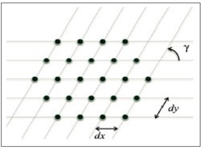
Figure 1: Hexagonal Perimeter with Equilateral Triangular Grid Array
Figure 2 shows two azimuthal angles to illustrate the six-way symmetry of this very narrow “pencil beam” profile. For a 950 m spacetenna having 6000 elements on a side, the beam spread is lower than one-tenth of a degree (0.1°) [6]. Although impressive, the subtended angle of a 10,000 m rectenna from GEO is just 0.015 degrees. At these small angles, the tangent is approximately equal to the argument, which means that either the spacetenna must be approximately six times larger or the rectenna six times larger, or some intermediate compromise.
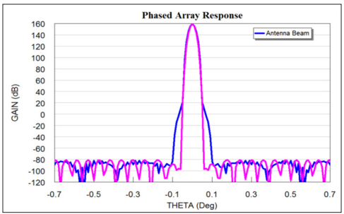
Figure 2: Pencil Beam Profile Showing -240 dB Sidelobe Level for 0 and 30 degrees Azimuth, having a 0.1° Spread
The discovery of a PAA architecture with 18 order of magnitude improvement over the current state of the art calls for further validation. One such study used a completely distinct software tool to simulate the pencil beam from a triangular arrangement of PAA elements within a hexagonal perimeter. This was performed using MATLAB® and the beneficial result was not only confirmed, but even shown to extend down to PAA sizes as small as 6 m at 5.8 GHz [7].
Figure 3 shows the elevation angle (θ) arrangement of a generic space-to-earth transmission arrangement. Note that azimuth angle (φ), in a plane perpendicular to this 2-D schematic, must also be considered. In all SBSP configurations, there will be gravitational perturbations of the powersat that require station keeping and/or electronic beam steering in order to maintain accurate pointing towards the rectenna. A key feature is the pilot beam directed from the rectenna ground station towards the spacetenna, this beam being used to determine angle of arrival (AOA) so that the power beam can be directed towards the intended target by analogue phase control of transmitting PAA elements.
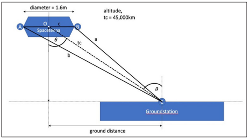
Figure 3: Arrangement Drawing for Spacetenna Receiving Pilot Siganl from Rectenna Site
The WPT community frequently cites phase conjugation as an elegant means by which to deliver the power beam along azimuthal angles that are the negative of the incoming pilot beam angle, hence returning the power beam generally towards the origin of the pilot beam. This method is currently in use with 5G cell phone signals. However, the radio-frequency (RF) microelectronics of phase conjugation circuits by their nature involve leakage and crossover of signals such that the phase conjugation process is less than ideal [8]. Advanced phase conjugation methods used in 5G applications over several 100s of meters can achieve 1° accuracy, which is adequate over such distances [9]. However, as noted above, GEO to Earth AOA applications must be approximately 66 times better than this.
Referring to Figure 3, the sites marked A and B represent sensing antennas at the extreme edges of the spacetenna, both detecting the pilot signal delivered by the ground station. In a practical system, there will be two orthogonal orientation angles for a spacetenna that will generally have both elevation and tilt angles relative to the rectenna. In this novel configuration, captured in a patent application pending with the US Patent and Trademark Office, the time-of-flight difference in the pilot signal arriving at points A and B can be used to obtain a high precision estimation of the AOA. Figure 4 shows a three-dimensional circuit configuration built to compare the signals arriving at A and B using a Phase-Frequency Detector (PFD). The PFD is highly sensitive to extremely small differences in phase, and can deliver superior AOA performance even across the immense distances between Earth’s surface and an orbiting powersat.
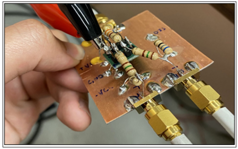
Figure 4: RF Circuit Board Hand-Soldered “Dead Bug” Arrangement for Phase-Frequency Detector (PFD) Circuit
Using PSPICE parameters provided by integrated circuit vendors, the Ansys EM Desktop software was used to predict performance of a phase-based time-of-flight AOA system. Commercial chips having phase-based time resolution of 1 ps (1E-12 s) are available. With a very small, modular PAA of just 1.6 m diameter, this translates into a ground error of just 35 meters and an AOA accuracy of 0.045°. This is a factor of 22 better than the best state-of-the-art phase conjugation circuit, and approximately 100 times improved over standard methods. Despite this remarkable improvement, an important consideration for both AOA approaches (time-of- flight and phase conjugation) is that small angles provide lower resolution than larger angles. This means that SBSP powersats that are not exactly at the nadir of their intended terrestrial rectenna will have superior pointing accuracy. This is good news for non-traditional SBSP architectures such as the Molniya orbit or trains of low earth orbit (LEO) constellations. This may also be advantageous for GEO architectures because most of the orbital slots that lie directly above population centers are already allocated towards communications purposes.
A final note to make regarding the AOA accuracy using the time- of-flight and PFD circuit is that higher accuracy may be realized by extending the accumulation times of the signal. In practice, this means that there exists a tradeoff between pointing accuracy and refresh/update rate. This is fortuitous because for GEO powersats and Molniya orbits which linger over their target rectennae, the angular rate of change is low. Thus, the accumulation period can be dynamically adjusted, based on the architecture, in order to maintain sufficient accuracy in AOA measurements. In this manner, WPT power beam aiming can be held to the center of the rectenna with high accuracy, regardless of architecture.
To validate time-of-flight simulation results, an experimental apparatus was constructed based on the 1.6 m diameter spacetenna that could be rotated relative to a pilot beam antenna.
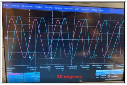
Figure 5: Oscilloscope Trace of Amplified Signals at 20° Rotation into Phase-Frequency Detector Circuit. Horizonal Scale has 5 ns/ div; the Vertical Scale is 1 V/div
Equidistant coaxial paths delivered sine wave signals from the A and B (Figure 3) to the inputs of the PDF (Figure 4). Figure 5 shows the amplified A and B signals at a 20-degree rotation. The phase difference between the blue and mauve traces is easily seen. Figure 6 shows the results of testing of rotation angles from -40° to +40°. The experimental relation is well-behaved between -30° to +30°, having an R-squared metric of 0.97.
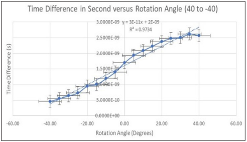
Figure 6: Measured Time Difference Across 1.6 m Versus Rotation Angle Showing -30° to +30° Detection Window
The PFD output is proportional to the time difference, which means that small angles will result in small signals. An analog- to-digital converter circuit works best with a signal that is larger than its minimum resolution, so accumulation of multiple signals is used to boost the signal level. Figure 7 shows the accumulation of signals over time for a 1 ps (blue) and a 3 ps (red) signal summed across a duration of just one microsecond. The vertical scale is in microvolts. These two cases represent powersats very close to the nadir, which is the worst-case scenario. It can be observed that the relation is sublinear, this being due to self-discharge of the accumulation capacitor. For longer accumulation times than 1 microsecond, which is reasonable and practical per the above discussion, this non-linear behavior must be accounted for.
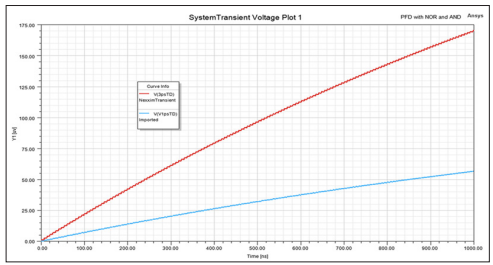
Figure 7: Accumulation of Individual Signals at 1 ps and 3 ps Time-of-Flight Differences in PDF (Simulated)
A final consideration in experimental measurements is repeatability. Figure 8 shows the results of single readings (not accumulated) for time-of-flight AOA of 12 degrees. The ratio of average to standard deviation is 48, with the 2-sigma spread being 46 ps. This point illustrates the importance of accumulating a signal, both to boost the value of the voltage to be read by the control electronics, and to average out the noise inherent in such signals.
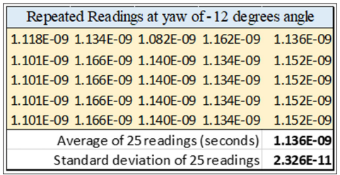
Figure 8: Repeated Measurments and Statistical Analysis of Time-of-Flight PFD Readings at a 12-Degree Angle
A true “pencil beam” with negligible SLL is an exciting discovery, but comes with two drawbacks. First, in forming such a high- precision beam, there is relatively low tolerance for failed elements across a large spacetenna. This will require vigilant maintenance and prompt replacement [10]. Second, the profile of per-element antenna power drops significantly from the center to the edge of a large antenna. Because of this, the perimeter elements are delivering a small amount of energy, which is unsatisfying from an efficiency perspective. Sparse arrays or truncated arrays are methods often proposed to address this consideration. However, such a profile is the penalty that must be incurred so that SBSP can achieve low off-axis power levels and thereby garner widespread acceptance, bringing its benefits to the world.
The time-of-flight (TOF) detection of AOA is two orders of magnitude better than phase conjugation, but it surrenders an important advantage. Phase conjugation is a local operation, whereas TOF is global to the transmit antenna. For rigid antennae this is a minor issue, but for very large, possibly flimsy, spacetennae, TOF requires that each element knows its displacement along the beam axis relative to its neighbors. This imposes additional design and engineering burdens on TOF in order to attain the high directional accuracy. Solutions may include dividing the spacetenna into smaller sectors, or employing positional detection devices that help modify antenna element phase signals to account for a non-flat PAA [11].
The problem of stray energy for SBSP has been solved. This relies on two innovations used together. The first is a breakthrough in tight beam formation that remained undiscovered until 2015. The second is a simple decoupling of pilot beam detection and phase angle delivery. Together, these represent a significant advance in the state of the art for WPT, and resolve two issues which were previously considered “show stoppers.” For accurate AOA detection, the PFD- based method presented here is far superior to phase conjugation. However, to achieve a reasonable signal strength, and to average-out noise errors, accumulation of the signal is needed. This is especially important when the elevation angle away from the nadir is small. Fortunately, this situation typically occurs when translation rates are low, such that long accumulation times (meaning low refresh rates) are acceptable and easily managed.
This work was funded in part by a research grant from Virtus Solis Technologies, Inc. Additional support came from the Richard G. Lugar Center for Renewable Energy. Portions of this work were conducted by A.J. Kragt Finnell, James Xue Lin Lok, Rayden Sia Zhen Ron, and Justin Stiers.
1.Van Wynsberghe E, Schubert PJ (2023) Metrics for Global Emissions Reduction using Solar Power Beamed from Orbit. Proc. of IAF Global Space Conf. on Climate Change (GLOC 2023) Oslo, Norway https://www.iafastro.org/assets/files/ publications/global-conferences/2023/GLOC%202023%20 FP_2023-05-19.pdf.
2.Hatsuda T, Ueno K, Inoue M (2022) Solar power satellite interference assessment. IEEE Microwave Magazine 3: 65-70.
3.McSpadden J (2015) Solar Power Satellite Technology and Frequency Selection. IEEE Wireless Power Transfer Conference 2015, Boulder, CO.
4.Schubert PJ (2023) Pencil Beams and High-Precision Aiming. Proc. of International (On-line) Conference on Energy from Space, ESA https://indico.esa.int/event/476/.
5.Dolph CL (1946) A Current Distribution for Broadside Arrays Which Optimizes the Relationship Between Beam Width and Side-Lobe Level. Proc IRE and Waves and Electronns 335-348.
6.Schubert PJ (2016) Sidelobe Reduction for GEO to Earth Wireless Power Transfer. Int’l. Astro. Conf. 2016, Guadalajara, Jalisco, Mexico. https://iafastro.directory/iac/paper/id/32221/ summary/.
7.Finnell AJ, Schubert PJ (2019) Antenna Arrangement Verification for Low Sidelobe Levels. IEEE WiSEE 2019, Ottawa, CN https://scholarworks.iupui.edu/items/53318194- 342b-435a-9328-0b385d3a8d8b.
8.Razavi B (2011) RF Microelectronics. Pearson https://picture.iczhiku.com/resource/eetop/ WYKgsQqKzSDpFmbM.pdf.
9.Fusco V (2009) High-Performance IQ Modulator-Based Phase Conjugator for Modular Retrodirective Antenna Array Implementation. IEEE Trans. Micro. Th. and Tech 57.
10.Finnell AJ, Heng P, Powell SH, Schubert PJ (2019) Spacetenna Flatness and Error Correction. Proceedings of the Int’l Astro. Cong. 2019, Washington, DC. Finnell AJ, Heng P, Powell SH, Schubert PJ (2019) Spacetenna Flatness and Error Correction. IEEE WiSEE 2019, Ottawa, CN.
View PDF