Author(s): BD Yadav*, Nilesh Choudhary, Jaydev Kumar Mahato, Nitin Kumar
The construction of high-rise buildings, both residential and commercial, is increasing. Every structural designer must be aware of the forces such as earthquake and wind effects. Every engineer is challenged to provide stability and strength for loads such as lateral forces (wind and seismic loading). That is why wind loading has become one of the most important issues in high-rise buildings. Lateral loads are crucial for drift; therefore, drift must be considered for high-rise structures. This research work focuses on the effects of various wind loads on high-rise structures with the provision suggested in IS 875(part 3):2015 and for seismic load using IS code 1893(part1):2016. For the study, four irregular plan building is used with G+20 story in seismic zone V and terrain category II with a basic wind speed of 44, 47, 50, and 55 m/s that is analyzed and designed using the structural analysis software tool STAAD Pro. The bending moment, shear forces, story displacements, story shear, and story drift are analyzed on every level of height on the building, and the results are compared with them.
In India, residents are increasing gradually, and the necessary land for a living. It is a key requirement to survive anywhere. For that reason, multi-story buildings are the best choice for construction in Metro cities where a smaller amount of property is presented [1,2]. As the designer knows multi-story structure provides a large floor area in a small area, it is also beneficial. Hence, it is required to assemble high-rise structures [3,4]. If high-rise structures are constructed, then many structural troubles come to pass, such as lateral load effect, lateral displacement, stiffness, etc. Normally for high-rise structures, wind and earthquake load effects prevail [5,6]. Therefore, for high-rise structures,s it is essential to know different loads and their effect on structure. There are many types of effects worked on structure and causes for failure [7,8]. The effect of lateral load is very important, such as earthquake and wind loads. In some cases, the wind load is more important than the earthquake load, which depends on the place and zone factors distinct by codes [9,10]. As previous studies say, wind load or wind effect is as dangerous as an earthquake. The defining wind, there are two aspects first one is helpful, which is to produce power and gives relief in a hot and humid environment, and the second one is parasitic, which comes out be a factor believed by engineers [11-13]. As a design engineer wants to be safe in his structure, this wind effect will cause and produce wind induce movement in the structure. As high-rise buildings move onward the envelope to larger heights, the structural designers are not only faced with difficulty in choosing a structural element to take the lateral load such as wind load and earthquake load but also ensure the design criteria that meets reliability and serviceability requirement under difficult wind environment[14-16]. Wind load is a lateral weight on buildings that act along and across the wind. In IS Code 875(part 3)-2015, the basic wind speed is specified on the map and categorized by zones. The shape and size of the building are very significant in wind analysis because the wind pressure is mainly depending on the exposed area of the building in opposition to wind speed [17-19]. Our country is in a developing stage with huge infrastructure development growth. The population is the main concern of our country, and it is necessary day by day; the land, mainly in India, is preserved for agriculture and farming, so there is a need for space for human dwelling. Hence development in vertical construction is necessary [20-22]. Present urban development shows a high increase in the construction of high-rise buildings. In a high-rise building, the lateral load is of prime concern. It increases with an increase in the height of the building. The structure design is done to take care of strength, rigidity, and stability. The most common loads of prime concern resulting from gravity are dead load and live load [23,24]. Besides these, loads of prime concern are wind load and seismic load. So, for the structure, it is very important to have sufficient strength against gravity load, i.e., dead load and live load, and adequate stiffness against the lateral load, i.e., wind and seismic load [25,26].
The structure is located in seismic zone v with a wind speed of 44, 47, 50, and 55 m/s, as suggested by IS 875(part-3):2015. The wind pressure is from the extent of the rigid diaphragms assigned to the slab elements.
The basic wind speed (Vb) for any shall be obtained and modified
to include the following effects to get the design wind velocity at
any height (Vz) for the chosen structure:
a) Risk Level
b) Terrain roughness, height, and size of the structure
c) Local topography
d) It can be mathematically expressed as follows: Vz =Vb k1
k2 k3
Where,
Vz = design wind speed at any height z in m/s
k1 = probability factor (risk coefficient)
k2 = terrain, height, and structure size factor
k3 = topography factor
The terrain category should be selected due to the obstruction effect and possesses the ground roughness surfaces. The direction of wind consideration depends on the terrain category. Wherever sufficient meteorological information is available about the wind direction, the orientation of any building or structure may be suitably planned. The terrain in which a specific structure stands shall be assessed as being one of the following terrain categories:
a) Terrain Category 1 - The structure is less than 1.5 m and has
no obstruction at the average height of any object exposed
to open terrain.
NOTE - This category includes open sea coasts and flat,
treeless plains.
b) Terrain Category 2 - Open terrain with well-scattered obstructions having a height generally between 1.5 and 10 m.
c) NOTE - This is the criterion for measurement of regional basic wind speeds and includes airfields, open parklands, and undeveloped, sparsely built-up outskirts of towns and suburbs. Open land adjacent to the seacoast may also be classified as Category 2 due to the roughness of large sea waves at high winds.
d) Terrain Category 3 - In this category, Terrain with numerous closely spaced obstructions has the size of building structures up to 10 m in height with or without a few isolated tall structures.
The following relationship between wind pressure and wind speed
shall obtain the wind pressure at any height above mean ground
level:
Pz
=0.6 Vz
2
Where,
P z
= wind pressure in N/m2
at height z,
V z
= design wind speed in m/s at height z.
The necessary formula is adopted for calculating the wind load on individual structural elements such as roofs and walls and individual cladding units and their fittings; it is necessary to consider the pressure difference between opposite faces of such elements or units. Therefore, it needed to know the internal pressure as well as the external pressure. Then the wind load, F, acting in a direction normal to the individual structural element or cladding unit is: F= (C pe-C subpi) A P z Where, Cpe = External pressure coefficient Cpi = Internal pressure coefficient A = Surface area of a structural element or cladding unit P z = Design wind pressure
Earthquake analyses for the structure are carried out, assuming lateral (horizontal) forces are equivalent to the dynamic or actual loading. The overall horizontal force, also called base shear on the building, is computed by considering the fundamental period of vibration, structural mass, and mode shapes. The total seismic base shear is divided along the structure's total height using lateral or horizontal force according to the formulae specified by the code. The following method is suitable for building with low to medium height and regular conformation.
This method is the simplest approach for seismic analysis of multistoreyed structures. In this method, the structure is considered to be elastic when contacted with static force. The lateral static forces are placed individually in two principal axes, i.e., transverse and longitudinal, and resulting internal forces are mixed up using combination methods. The building to be analyzed by the linear static method should contain some criteria for its stiffness and geometrical regularity.
a) All members, such as columns and walls resisting lateral loads, should move from bottom to top.
b) The lateral stiffness and mass should not vary suddenly from bottom to top
c) Certain values must be maintained in the geometrical asymmetries in height or layout plans.
This procedure is very suitable and simple for a structural engineer to execute a seismic analysis for reasonable outcomes. This method is widely used for buildings and structures with regular conditions.
In this study, four 3D RC framed model structure of G+20 (Fig. 1-3) has been analyzed and designed using the software STAAD Pro in zone v having wind speed of 44, 47, 50, and 55 m/s in medium soil with topography category II, response reduction factor 5, effective damping 5% and importance factor 1, the IS codes used as per Indian norms. IS 456:2000, IS 875(part3):2015 and IS 1893(part1):2016.
a) G+20 RC Framed structure with a basic wind speed of 44
m/s
b) G+20 RC Framed structure with a basic wind speed of 47
m/s
c) G+20 RC Framed structure with a basic wind speed of 50
m/s
d) G+20 RC Framed structure with a basic wind speed of 55
m/s
The complete parameters and their description of the RC framed structure used in given in the tabular form below (Table 1):
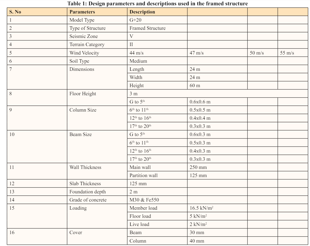
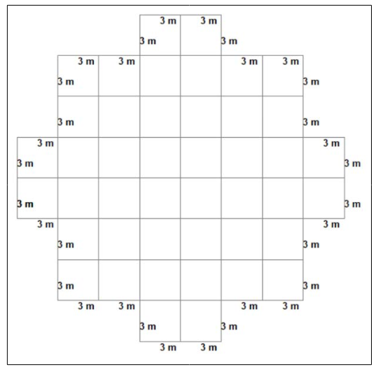
Figure 1: Plan of G+20 Framed Structure
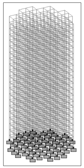
Figure 2: Isometric View of G+20 Framed Structure
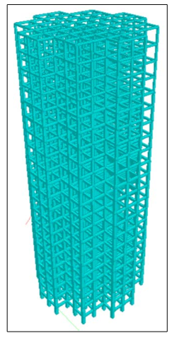
Figure 3: 3D view of G+20 Framed Structure
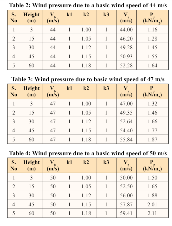
Wind load is calculated as per IS 875(part3):2015
Terrain Category II
Wind load calculation of various wind speeds used in the framed
structure is given in the tabular form below (Table 2-5):
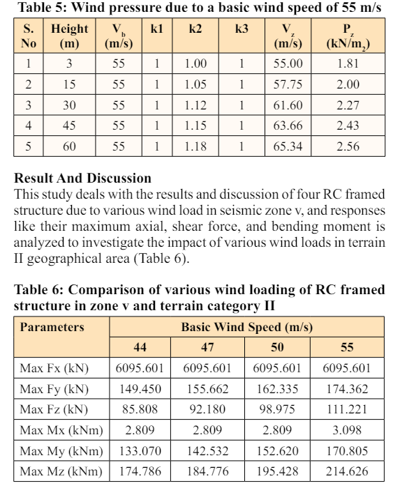
The behavior of the RC framed structure in various wind loading in terrain category II and Zone V was studied, and the following conclusions were observed from the analysis of this research
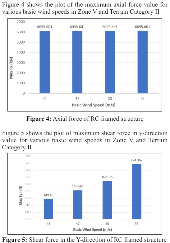
1. Shear force variation
(a) In the x-direction, as we compared with various wind loading, an axial force is constant or the same in each basic wind speed.
(b) In the y-direction, the shear force is 4.15% more at 47m/s compared to 44m/s, and the shear force is 4.28% more at 50m/s compared to 47m/s, and shear force is 7.41% more at 55m/s as compared to 50m/s.
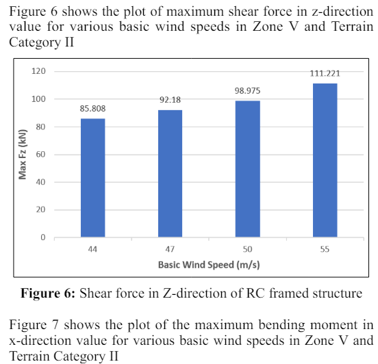
(c) In the z-direction, the shear force is 7.37% more at 47m/s as compared to 44m/s, and the shear force is 7.42% more at 50m/s as compared to 47m/s, and shear force is 12.37% more at 55m/s as compared to 50m/s
2. Bending moment variation
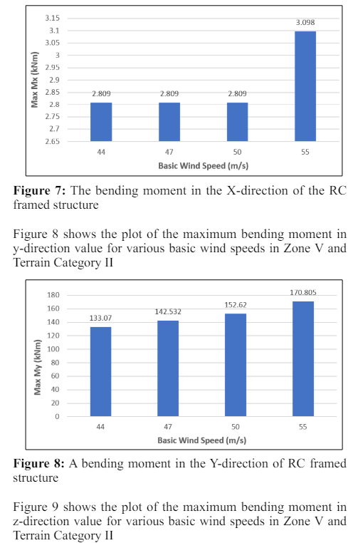
(a) In the x-direction, as we compared 44m/s, 47m/s, and 50m/s, the bending moment is the same, but in 55m/s, it is 10.28% higher than the rest.
(b) In the y-direction, a bending moment is 7.07% more in 47m/s as compared to 44m/s, the shear force is 7.11% more in 50m/s as compared to 47m/s, and shear force is 11.91% more in 55m/s as compared to 50m/s.
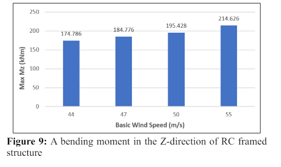
(c) In the z-direction, a bending moment is 5.71% more at 47m/s as compared to 44m/s, the shear force is 5.76% more at 50m/s as compared to 47m/s, and the shear force is 9.82% more at 55m/s as compared to 50m/s.
3. It is found that the variation of shear force and bending moment is very much severe in basic wind speed of 55m/s in Terrain category II and Zone V. So, the structural designer needs to design the high-rise structure in that region.